In the following study, LINK3D was used to generate a high quality hexahedral mesh for an advanced inward turning scramjet inlet. A scramjet engine is a thrust producing device that operates at supersonic conditions and has essentially no moving parts. A scramjet flowpath has four basic components: an inlet, an isolator, a combustor, and a nozzle. The inlet raises the temperature and pressure of the flow as it enters the engine. The isolator acts as a flow conditioner and buffer between the combustor and inlet. The combustor is the location for fuel injection, mixing, and combustion. The nozzle produces thrust by expanding the hot gases as they exit the engine.
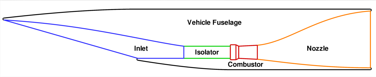 Basic scramjet engine components.
The scramjet inlet geometry shown here was generated using a Busemann streamline tracing code. This code generates a set of ordered points which were subsequently converted to CAD surfaces. The inlet geometry was imported into LINK3D using the STEP file format. After importing the model, an inflow surface was created using the Geometry workbench. Then, curve and surface groups were created to highlight relevant geometric features. After geometry grouping was complete, the surface topology for the inlet and cowl was created. Then, the entire surface topology was extruded to create a boundary layer wrap. With the boundary layer blocks created, the isolator flowpath was completed using the standard O-H topology. The topology extrusion process was repeated until the tip of the inlet was reached. Finally, the outermost topology was selected and extruded to the inflow boundary.
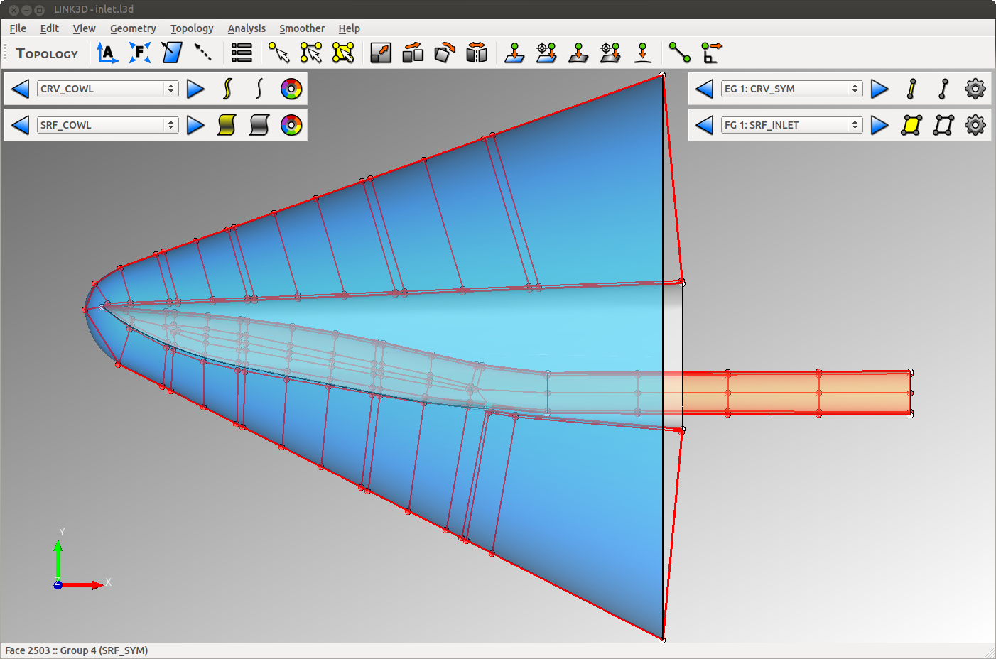 Inward turning scramjet inlet geometry and topology.
The resulting grid topology had 740 blocks with 9 million cells in the half mesh. Viscous clustering (1.0E-6 m wall spacing, 70 cells) increased the total cell count to 19.6 million cells. The total mesh generation time for smoothing, clustering, and export required 100 minutes on 128 cores (two nodes with 4x AMD Opteron 6272 CPU’s per node). The total user time for geometry processing and topology creation required one work day to complete. Due to the flexibility of the topology-based approach, design changes to the inlet and engine flowpath can be re-meshed very quickly. For example, an efficient user can generate and analyze ten or more inlet geometries per week.
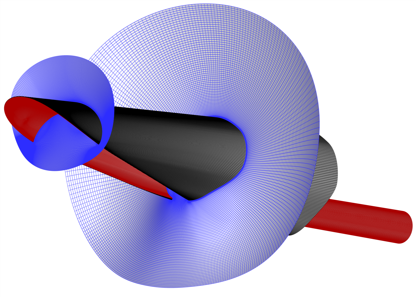 Surface mesh and volume grid sheets for inward turning scramjet inlet.
The highly swept three-dimensional nature and large range in length scales of the inward turning inlet geometry makes it a very challenging problem for mesh generation. To compound the problem, the inlet operates under hypersonic flow conditions (Mach 5+) which produce strong shock waves, extremely thin boundary layers, and complex flow structures. It is well known that the accuracy of hypersonic flow simulations are highly sensitive to grid quality, flow feature alignment, and boundary layer resolution. It has also been shown that unstructured meshes (those that use tetrahedra, pyramids, prisms, and other) produce spurious errors across strong shock waves and in regions with strong shock interactions. Structured meshes, however, have been found to show improved accuracy for hypersonic flow simulations due to their isotropy, flow feature alignment, and smoothness of resolving length scales.
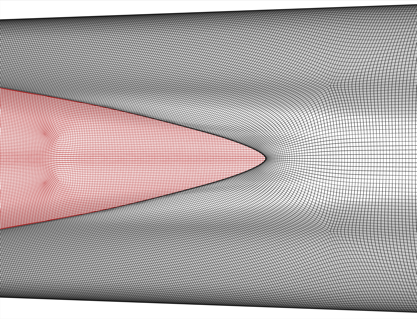
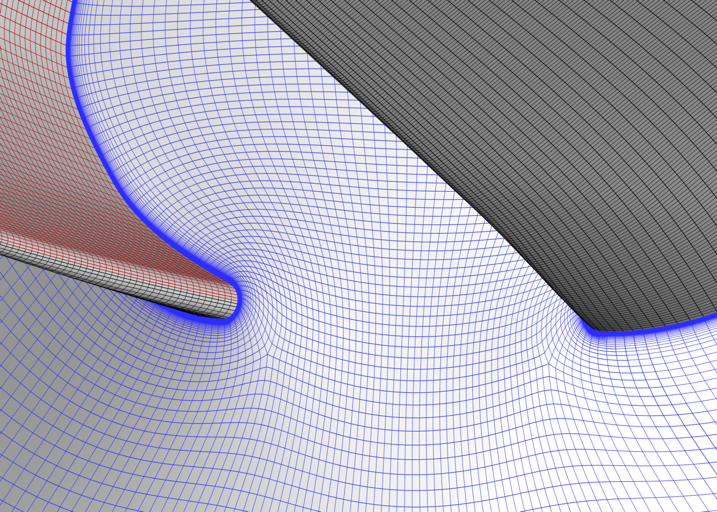 Leading edge region showing surface mesh and volume mesh.
Another factor that influences the accuracy of hypersonic flow simulations is the presence of grid singularities. Singularities are locations in the mesh where the computational directions (i,j,k) are not unique. In structured meshes, 3-block and 5-block singularities are used to increase or decrease the mesh resolution.In unstructured tetrahedral meshes, every point in the grid can be considered a singularity. In practice, singularities are introduced as needed to increase or decrease mesh resolution. However, users should try to use grid singularities in regions where they will have minimal impact on solution accuracy.
 Inlet and cowl surface mesh as viewed from bottom.