In the following study, LINK3D was used to generate a high quality hexahedral mesh for a ducted submarine propulsor. A typical ducted propulsor has four main components: a hub, a cowl, a set of radial struts, and a multiple bladed propulsor. In the example shown here, the assembly has five struts and a three-bladed propulsor. The standard approach for modeling propulsor geometries is to break the volume into a non-rotating section that includes the struts and a rotating section that includes the propulsor.
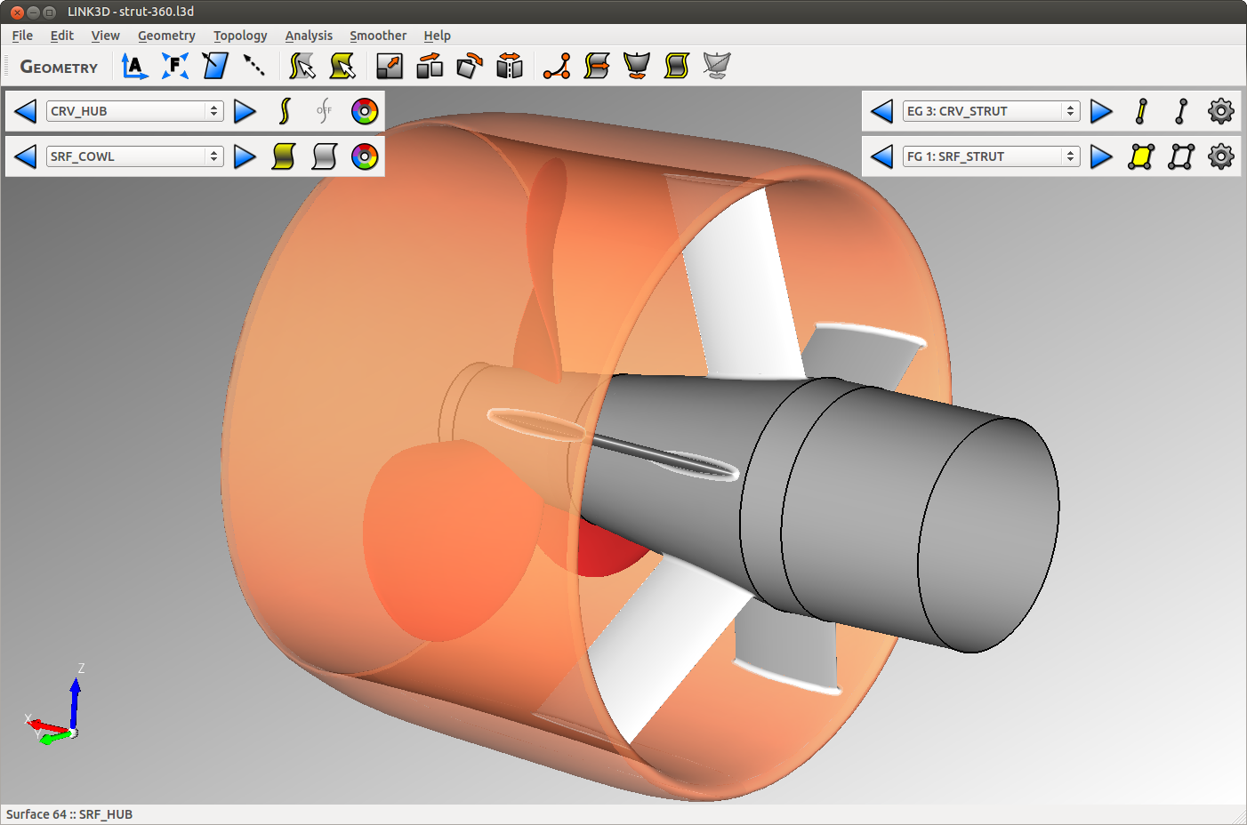 Ducted propulsor geometry showing hub, struts, cowl, and propulsor.
The surface topology for the strut was created using feature curves at the root, tip, and leading edges of the strut. The surface/volume topology was constructed for one fifth of the model and copied and pasted using the rotation operator. LINK3D makes this process straightforward by automatically copying edge and face group settings to the newly created entities.
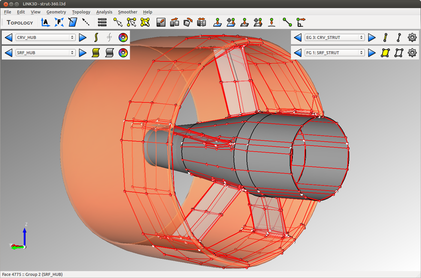 Ducted propulsor surface topology within strut section.
The final volume grid for the strut section contains 1,440 blocks with 12 million cells in the unclustered mesh. A continuous boundary layer wrap encompasses the cowl, struts, and hub. Mesh singularities allow the strut and cowl leading edges to be precisely modeled.
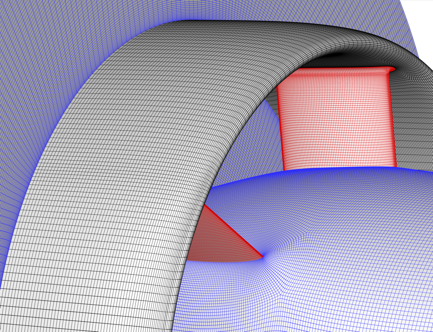 Surface and volume grid detail around struts.
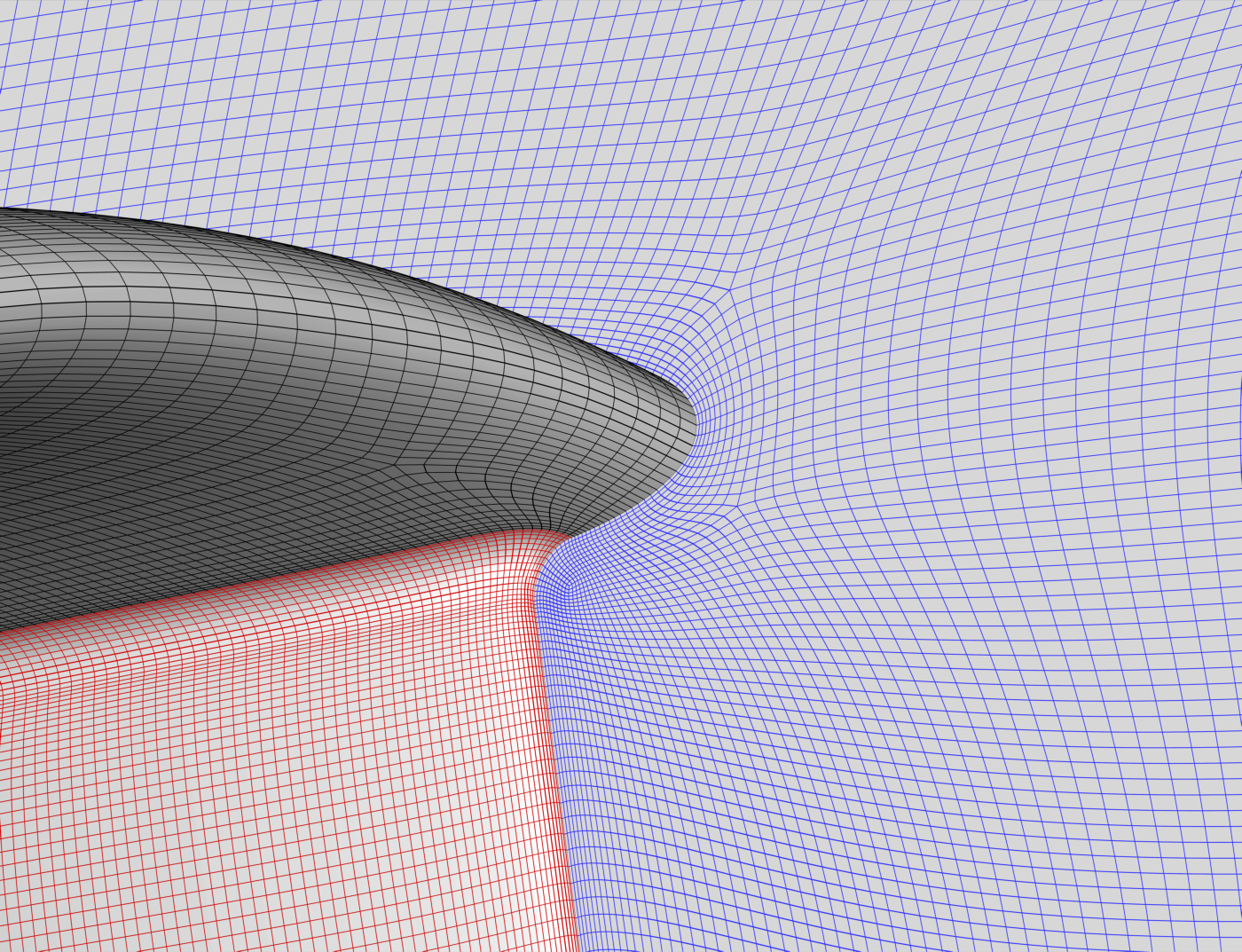 Surface and volume grid detail near cowl and strut leading edge.