In the following study, LINK3D was used to generate a high quality hexahedral mesh for the complete internal flowpath of GHI’s high speed wind tunnel. The wind tunnel feeds high pressure air through the feed tube and into the showerhead (left, blue). The showerhead acts as a flow regulator as each of the radial tubes become choked. The showerhead increases the pressure in the plenum which causes the air to move through the converging and diverging nozzle of the facility (middle, orange). The flow becomes sonic at the throat and expands to Mach 4 at the exit of the nozzle. The test section is defined as a rhombus of relatively uniform flow that near the exit of the nozzle. This is where the wind tunnel model is inserted. Finally, the flow enters the diffuser, passes through a muffler, and exits the facility.
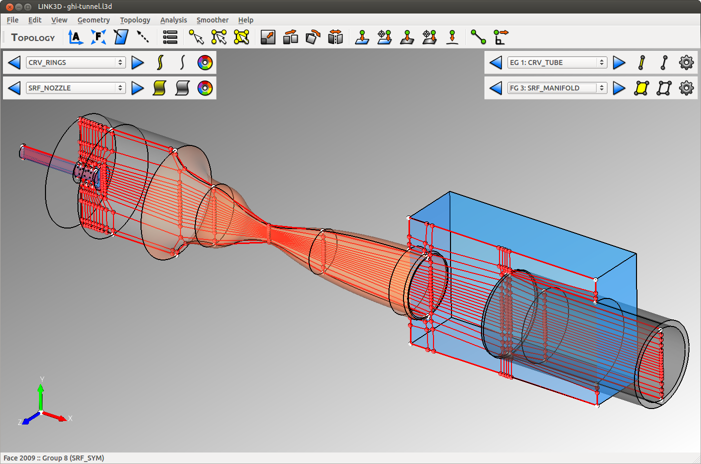 Supersonic wind tunnel facility geometry and topology.
The initial wind tunnel geometry was imported from a STEP file which contained more geometric information than needed for the CFD model. The extra CAD entities were quickly deleted to make the model more manageable. Using the Geometry workbench, the nozzle backbone curves were swept about the axis to create the converging and diverging surfaces. The plenum and diffuser were then created using the curve and surface tools in the Geometry workbench. Next, curve and surface groups were created to define each of the relevant geometric features. The surface groups consisted of the feed tube, showerhead, tubes, plenum, nozzle, box, and diffuser. After grouping the geometry, the topology creation process began with the most complicated feature, the showerhead. The basic process was to create the surface mesh for the feed tube, add topology around the radial tubes, and finish the surface topology on the showerhead. The surface topology was then extruded to create the boundary layer wrap. Then the feed tube and radial tube volume topology was completed. After a bit of work, the plenum topology was created and then extruded downstream through the nozzle, test section, and diffuser. Finally, the outer box region was added to complete the topology. The total time for geometry processing and topology creation required about three days.
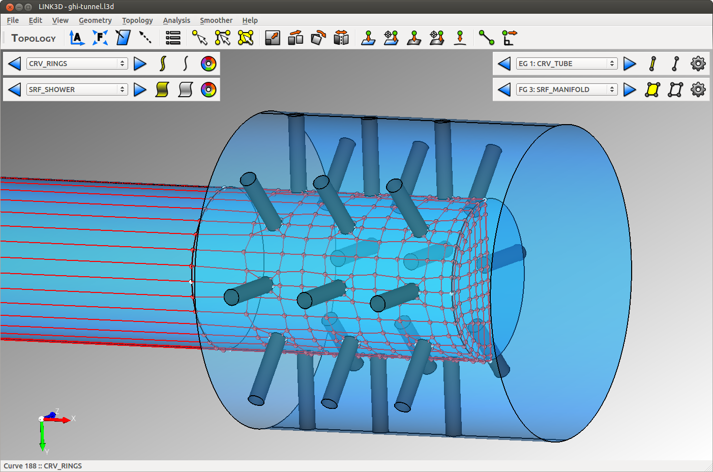 Surface topology for plenum shower head.
The final grid topology has 3,680 blocks with 16.2 million cells in the mesh before viscous clustering is applied. Viscous clustering brings the total cell count to 30.9 million cells. The total mesh generation time for smoothing, clustering, and export required less than three hours on 256 cores (four nodes with 4x AMD Opteron 6272 CPU’s per node). Once the topology is completed, the grid resolution, viscous clustering, and boundary conditions can be easily adjusted. In addition, geometry can easily be changed with minimal user effort. For example, changing from the Mach 4 nozzle to the Mach 3 nozzle would require fifteen minutes of user interaction plus by the computing time required for the grid generation run.
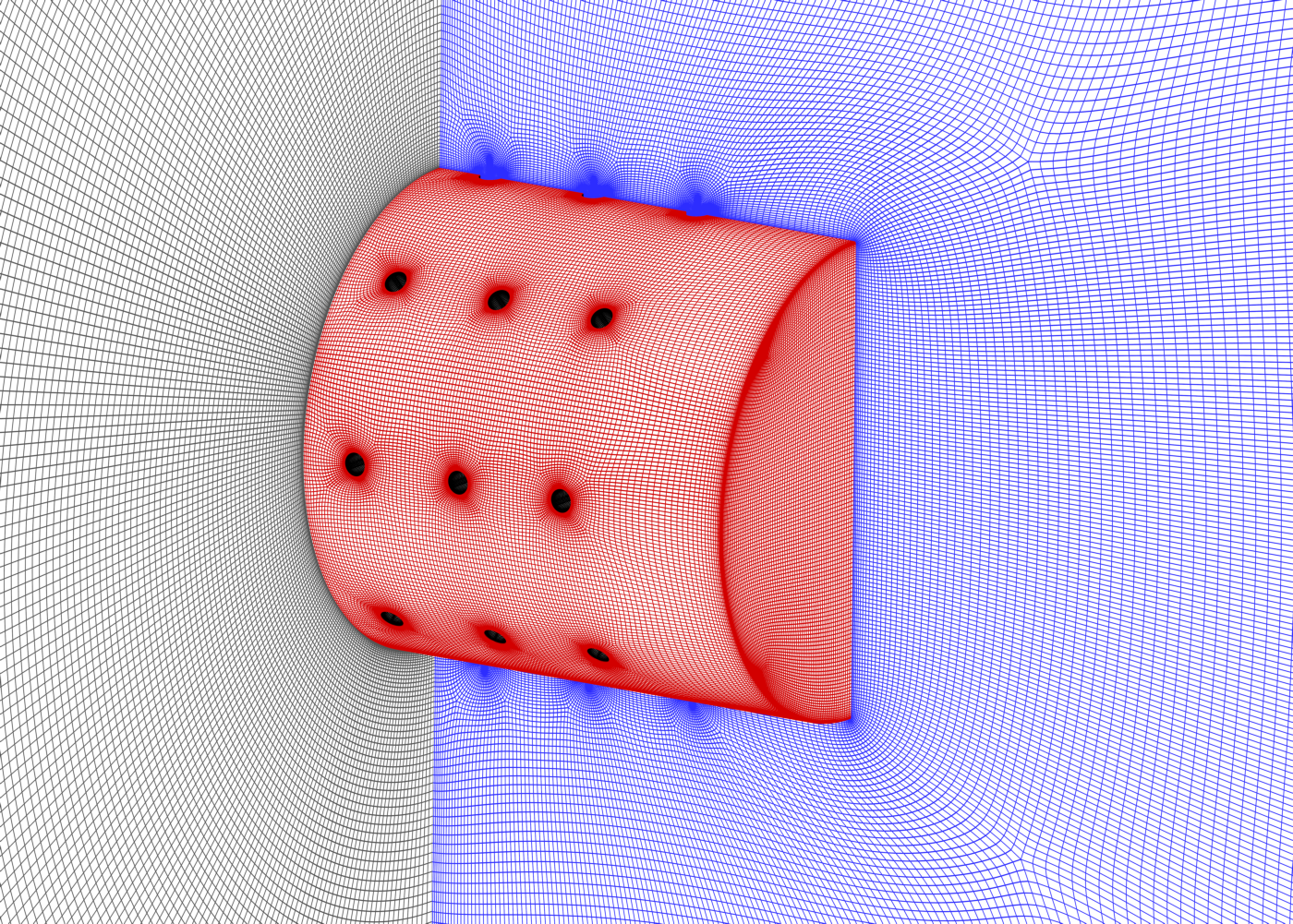 Surface mesh on plenum showerhead.
A computational fluid dynamics (CFD) solver was used to simulate the unsteady start up process of the wind tunnel. To initialize the flow, the entire volume was set to the ambient air conditions. The inflow boundary of the high pressure feed tube was set to the nominal tank pressure for Mach 4. The simulation used a detached eddy simulation (DES) model with 4th order spatial fluxes and 2nd order time integration. During the early phases of the simulation, the time step was limited to ~0.05 microseconds. Then, as the flow began to evolve the timestep was increased to ~1 microsecond for the remainder of the simulation. The simulation required nearly 100,000 iterations to start the tunnel, which represented approximately 0.1 seconds of physical time. All told, the simulation required over three weeks of continuous computing time on 640 cores (ten nodes with 4x AMD Opteron 6272 CPU’s per node).
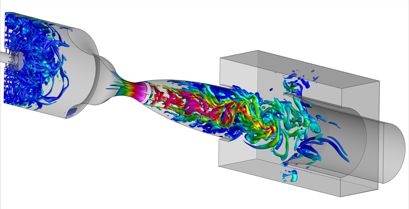 Isosurfaces of Q-criterion at one instance in time.